Just in time for Halloween! ...2017.
This idea started for a work Halloween costume party a few years ago – I was working in retail distribution centres and we decided it would be fun to dress up as superheroes based on the common devices we worked with. There was Horn Man, Prox (as in proximity sensor) Girl, Captain Carton, and more. I claimed the lowly strobe lamp, and decided to go the evil nemesis route by creating the character Strobulon.

A simple concept: a big helmet that acted as a strobe light, and a voice changer to sound extra evil. Naturally, I took it a little too far.
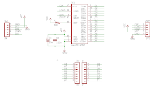
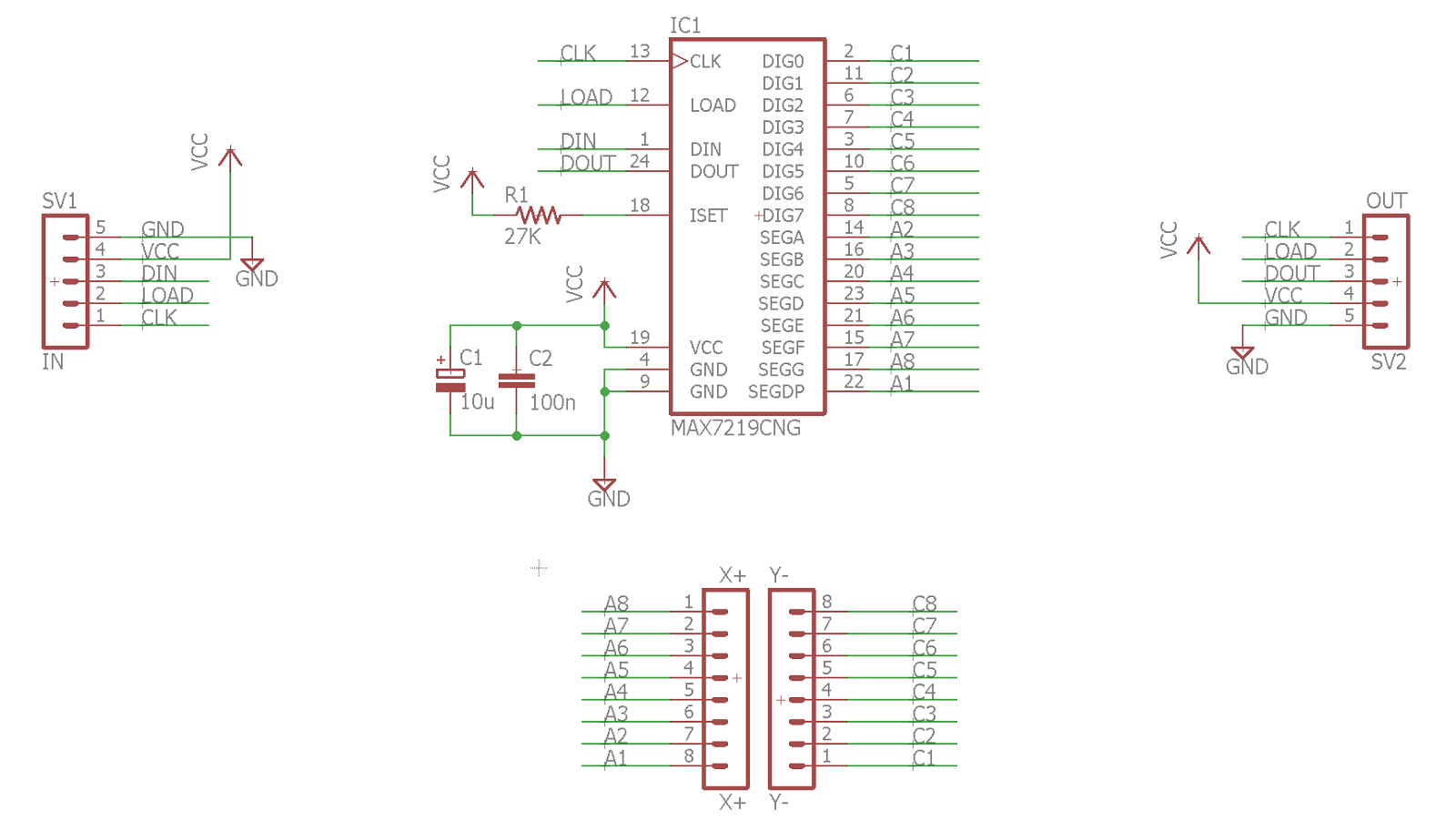
Here's the schematic I put together which breaks out the LED driver:
I decided to space my LEDs about an inch apart. Because of course, the bucket I purchased wasn't a perfect cylinder, but gradually tapered. So, I maintained a consistent vertical 1" spacing, but had to carefully adjust the horizontal spacing to accommodate for a changing bucket diameter.
After I had marked a grid of dots, and roughed out spaces for eyes and mouth, I proceeded to notch each mark with a push-pin. The idea was to ensure the drill bit wouldn't slip when punching the hole. While manually pushing a pin and then drilling a hole… 307 times isn't exactly fun, it paid off. No mistakes were made!
The 3/16" bit was perfect for this situation. It's just a teensy bit smaller than the diameter of a standard LED, and therefore I could push the LED through and it would firmly stay put without the need for glue. That said, my fingers were incredibly sore from pushing that many LEDs through tight spaces.
It's starting to come together!

The LEDs are linked together by row/column, and so with some clever bending and taping, I was able to use the exiting leads to tie all the lights together into a grid. Just 614 solder joins in an afternoon, no big deal.

Once the LEDs were in, they needed to be connected up to the drivers. I decided to try a PCB printing service (http://dirtypcbs.com/) to make the breakouts and make my life a little easier.
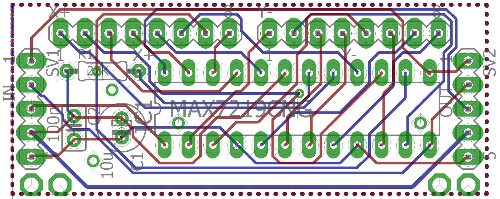
Here's the board layout (pre-ground-fill)

I was pretty happy with the end result!

The super-observant will notice that the helmet is 9 LEDs tall, and 32 LEDs around. This meant that I had 4 nice 8x8 matrixes to work with, and a weirdo configuration managing the bottom row of LEDs as well at the LEDs used in the eyes. Each row and column of each matrix had to be wired up to the breakout board. So much soldering.

Pro-tip: while you can use all the same coloured wire for a job like this… if you have access to multiple colours of wire you can likely save yourself some headache. The photo above actually has some bad wiring on the eye LEDs, and it was quite the pain to figure out how to rewire it properly without tearing it all apart.
A test of my wiring (and an attempt at a morale booster) as it was coming along:
Next, I integrated the voice changer fairly simply – took the toy apart and rewired it to connect to new Super Bright Red LEDs for the mouth, glued the microphone on the inside closer to where my mouth would be, and stuck the speaker and control board up top with the rest of the hardware.
Finally, once all the inside wiring was done, I cut a cardboard insert to wrap around the inside, and tied the internal strapping of one of my hardhats to the top (or… bottom) of the bucket to keep it all in place on my skull.

It ain't pretty, but it's what's on the outside that counts!
All wired up:

The Arduino IDE has a ready-made LedControl library for these chips which saves a ton of time. Using this, I really only needed to focus on coming up with cool patterns to play through! You'll notice I segregated that weird fifth LED driver to a separate bus for clarity.


Posing by a dumpster:


Maybe for my next costume party I should just go as a ghost... but I'm pretty happy with how this worked out!
This idea started for a work Halloween costume party a few years ago – I was working in retail distribution centres and we decided it would be fun to dress up as superheroes based on the common devices we worked with. There was Horn Man, Prox (as in proximity sensor) Girl, Captain Carton, and more. I claimed the lowly strobe lamp, and decided to go the evil nemesis route by creating the character Strobulon.

A simple concept: a big helmet that acted as a strobe light, and a voice changer to sound extra evil. Naturally, I took it a little too far.
Phase 1: Design
I had worked with hand-built LED matrixes before, and so I naturally gravitated to that solution. I just needed some bright yellow LEDs to wrap around some sort of helmet, and it was a plus that I could reuse the somewhat expensive LED controller chips I had lying around from an old project. For the voice changer, I decided to be lazy, and just hack apart an off the shelf toy. To control it all, I thought I'd finally take my Raspberry Pi for a spin doing real hardware work.Shopping list:
- 300x Super Bright Yellow LEDs for the helmet [SparkFun]
- 25x Super Bright Red LEDs for the eyes/features [SparkFun]
- 5x LED Display Drivers [SparkFun]
- 200 feet of thin 30AWG yellow wire (to blend) [SparkFun] [Amazon]
- Voice Changer [Amazon]
- Helmet! After much humming and hawing I went with the classic bucket [Home Hardware]
Yes, I put the bucket over my head in the store to make sure it fit. No regrets. - Raspberry Pi or Arduino
- Power Source (I went with a USB power bank I already owned)
Tools:
- Soldering iron – I eventually wound up buying a cordless unit, as my desktop iron was hard to work with in a confined space [Amazon]
- Drill with 3/16" bit
- Extreme patience and tolerance for pain (mental and physical)
Here's the schematic I put together which breaks out the LED driver:
Phase 2: Physical Development
To keep things interesting, I'm going to breeze through the careful planning I did here. If anyone is actually crazy enough to embark down the path of building something like this, let me know, and I will point you toward some great therapists.I decided to space my LEDs about an inch apart. Because of course, the bucket I purchased wasn't a perfect cylinder, but gradually tapered. So, I maintained a consistent vertical 1" spacing, but had to carefully adjust the horizontal spacing to accommodate for a changing bucket diameter.
After I had marked a grid of dots, and roughed out spaces for eyes and mouth, I proceeded to notch each mark with a push-pin. The idea was to ensure the drill bit wouldn't slip when punching the hole. While manually pushing a pin and then drilling a hole… 307 times isn't exactly fun, it paid off. No mistakes were made!
The 3/16" bit was perfect for this situation. It's just a teensy bit smaller than the diameter of a standard LED, and therefore I could push the LED through and it would firmly stay put without the need for glue. That said, my fingers were incredibly sore from pushing that many LEDs through tight spaces.
It's starting to come together!

The LEDs are linked together by row/column, and so with some clever bending and taping, I was able to use the exiting leads to tie all the lights together into a grid. Just 614 solder joins in an afternoon, no big deal.

Once the LEDs were in, they needed to be connected up to the drivers. I decided to try a PCB printing service (http://dirtypcbs.com/) to make the breakouts and make my life a little easier.
Here's the board layout (pre-ground-fill)
I was pretty happy with the end result!

Note that I used some of the board real-estate to make a relay breakout too.
The super-observant will notice that the helmet is 9 LEDs tall, and 32 LEDs around. This meant that I had 4 nice 8x8 matrixes to work with, and a weirdo configuration managing the bottom row of LEDs as well at the LEDs used in the eyes. Each row and column of each matrix had to be wired up to the breakout board. So much soldering.

Pro-tip: while you can use all the same coloured wire for a job like this… if you have access to multiple colours of wire you can likely save yourself some headache. The photo above actually has some bad wiring on the eye LEDs, and it was quite the pain to figure out how to rewire it properly without tearing it all apart.
A test of my wiring (and an attempt at a morale booster) as it was coming along:
Next, I integrated the voice changer fairly simply – took the toy apart and rewired it to connect to new Super Bright Red LEDs for the mouth, glued the microphone on the inside closer to where my mouth would be, and stuck the speaker and control board up top with the rest of the hardware.
Finally, once all the inside wiring was done, I cut a cardboard insert to wrap around the inside, and tied the internal strapping of one of my hardhats to the top (or… bottom) of the bucket to keep it all in place on my skull.

It ain't pretty, but it's what's on the outside that counts!
Phase 3: Software Development
I started this project with the idea of using my Raspberry Pi to talk to all the LED drivers, and also play with some audio processing to, say, have the lights react to music, and maybe even find a way to roughly display video (though that has limits when using single-coloured LEDs). Unfortunately, once I reached the point where I could start programming (the weekend before the party), my Raspberry Pi started randomly crashing and being generally unreliable. So, I fell back to the tried and true Arduino platform, and decided I was OK with limiting my project scope to just controlling LEDs with pre-defined patterns.All wired up:

The Arduino IDE has a ready-made LedControl library for these chips which saves a ton of time. Using this, I really only needed to focus on coming up with cool patterns to play through! You'll notice I segregated that weird fifth LED driver to a separate bus for clarity.
The Code
Phase 4: Final Touches
As you can see in a lot of the photos, the LEDs that are directly aligned with the camera are super-duper bright, while the rest aren't so much. Unfortunately, the LEDs I used have a bit of a narrower viewing angle. To remedy this, and to snazz things up a bit, I got a sheet of thin acrylic plastic to wrap around the helmet and diffuse the light.
I read online that in order to effectively bend acrylic, you need to heat it to around 300 degrees Fahrenheit. Initially I tried using my heat gun, and found that I couldn't get the plastic to warp at all. So, I tried it in the oven (as was suggested at the plastic store and online).
As you can see here, it worked great! I rolled a perfect cylinder:

Sadly I only bought one sheet of plastic, and anyway, the plastic was the least opaque they sold (before clear) and it still was too opaque. I'll try this experiment out again some time later, as I think it will really clean things up nicely.
Phase 5: Showboating
That's "all there is to it"! Now begins a new era of glamourous living.Posing by a dumpster:


Maybe for my next costume party I should just go as a ghost... but I'm pretty happy with how this worked out!
Comments
Post a Comment